Had done all my testing and flying on this version. Found some bugs and fixed it. The problem was during 3.6v and above the output will be getting higher linearly. So I had added a diode with a 0.6v forward drop voltage. This enables it to have a stable output at 3.3v.
This board design is only meant for 1S. Meaning operating voltage is in between 2.0v ~ 4.2v. Higher than that you need to modify the buckbooster part into a 3.3v LDO as well as the 5v power line to a 5V LDO. I modified this from OMNIBUSF4PRO to my custom made version. I removed SDCard as the blackbox to save more space for the All-In-One board.
For the USB port, I am not supplying the 5V to the board. It needs to be power up from the 1S battery. I dont want it to overload my laptop 5V to it or maybe accidentally shorted the board cause the laptop 5V logic all burned off. That is why I designed it not to supply to the board but needs to power up with the battery or some power supply regulator to the board before the USB port is recognized by the laptop or PC.
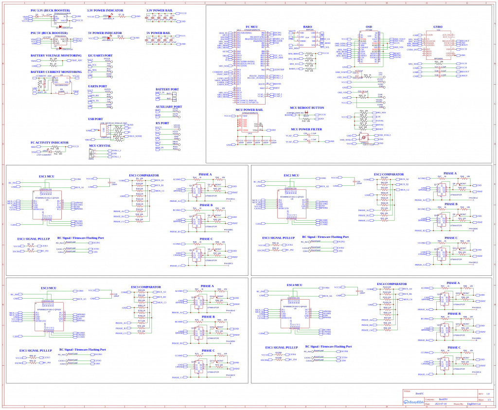
For the ESC part, is designed to be running on 1S. The MOSFETS are running at 5A maximum at continuous and pulse drain at 12A. Due to the ESC I had flashed with BlueJay, it should be able to handle a bit more then 5A. The trigger level (Vgs) of the MOSFET is very low, there isn’t need any MOSFET drivers. The only thing, we need to invert the output from one of the line to drive the P-MOSFET. If intended to driver higher current, try to find another type of MOSFET and replace it. The ESC design also can be used those single MOSFET rather 2-in-1 MOSFET. It will be bigger but reliability wise should be better. When designing a higher voltage ESC, meaning more than 1S, you will need higher current rating of the MOSFET and may need to add a driver or custom transistor to drive the MOSFET. I will be working on higher “S” ESC in near future. These designs are came from tinyPEPPER – https://fishpepper.de/projects/tinypepper/ with some modifications done to the schematic where it enables it to run at a very low voltage to provides stable 3.3v to the EFM8BB21F16G and is sharing with the main board FC’s 3.3v powerline. This will save some costs of making this FC. One 3.3v buckbooster that powers up the FC, Gyro, Baro, VTX, Cam, ESC and etc. It will not draw more than 1A as I had tested so far. The VTX is powered up by another 5V buckbooster power line. So is totally not affecting each other.
For the FC firmware, I am using INAV 3.0.1. I am a INAV fans. For betaflight it will work too but need to changed to OMNIBUSF4 board for the firmware.
Initially, the ESC’s EFM8BB21F16G are blank. You need to flash in the firmware using C2CK and C2D pins before you can flash the ESC firmware over serial passthrough method. Once if flashed, all ESCs will be appeared in the INAV configurator. You even can use the BLHeli or BlueJay configurator to set your preferred settings. If you need to know how to flash in the ESC firmware, you can read from here -> https://www.bertfpv.com/how-to-flash-blheli_s-firmware-to-efm8bb21f16g/. You will be able to have a full control of your hardware and without fear of broken it again.
I will include the gerber file on the next version. For this version, I still need to fix the distance between the pads and the SMD components. It needs a very steady hand to solder the wires on it. So I am going to built version 2.0 very soon.
Sponser this project:
https://www.buymeacoffee.com/bertfpv
Below is the schematic diagram for this All-In-One flight controller I had built. I had included both PDF and PNG. Time to built it your own and fly it. Is a very great experience and understanding how the whole quad works. Stay tune.
