Since day one I am on this RC hobby, I never had any aftermarket Radio Controller Transmitter. I had bought a broken Futaba Radio Controller and stripped off all the components inside the case and just left only the toggle switches and the gimbals. I linked them to my arduino nano for the first version that I have. I was using a very long antenna to maximize the 2.4G range.
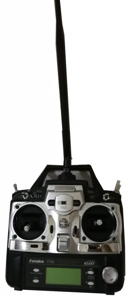
Later on, found that need a display to monitor the status and all the readings and decided to strip away the display and become a fully own custom version with display. Of course the case still a normal RC Transmitter case.
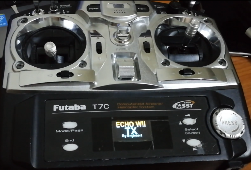
Had been using this a while and keep trying to learn flying at that time. Didn’t noticed about the precision I need that time. This Futaba gimbals are analog and the readings are about +-10% accuracy. Well, I was flying stable mode at that time and was enough for me.
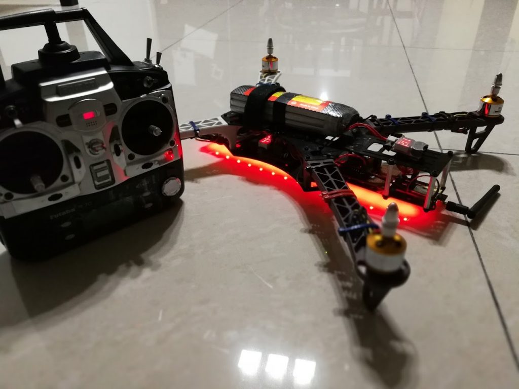
So once I am getting used to what I need, I had built a few racing quads with my own custom receiver and custom RC Transmitter. Until I had reached my limits and found out that actually I need something that are more precise in gimbal readings and faster processing microcontroller. I had upgrade from ATMEGA328 to STM32F1 chipset. But this also not for pretty long because I cant get what I need and the flexibility I wanted. Within the same year, I had upgrade to another version where the Radio Control Transmitter is totally 3D printed with FrSky M10 Gimbal Hall Effect sensor, ESP32, EByte E01-2G4M27D (Replica of nRF24L01) with 5km range and custom charging and 4 toggle switches. It was a development stage and the look of it like frankenstein because everything is opened.
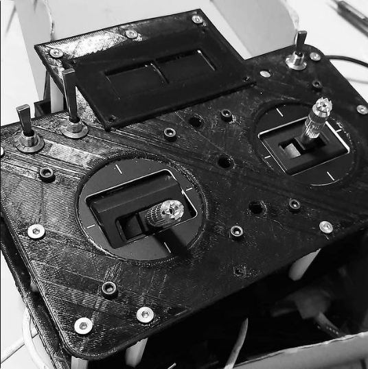
It comes with dual OLED, for the fun of it and is running on ESP32 with BLE, WiFi and lots of computation power. I love this so much. The problem of this was a bit clunky and a bit opened. Very vulnerable from water that splashed in if is raining and so on. Well, I finally ditched off everything migrated to a better version and better designed of the Radio Controller Transmitter.
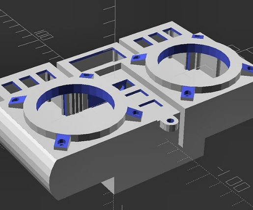
And the out come……
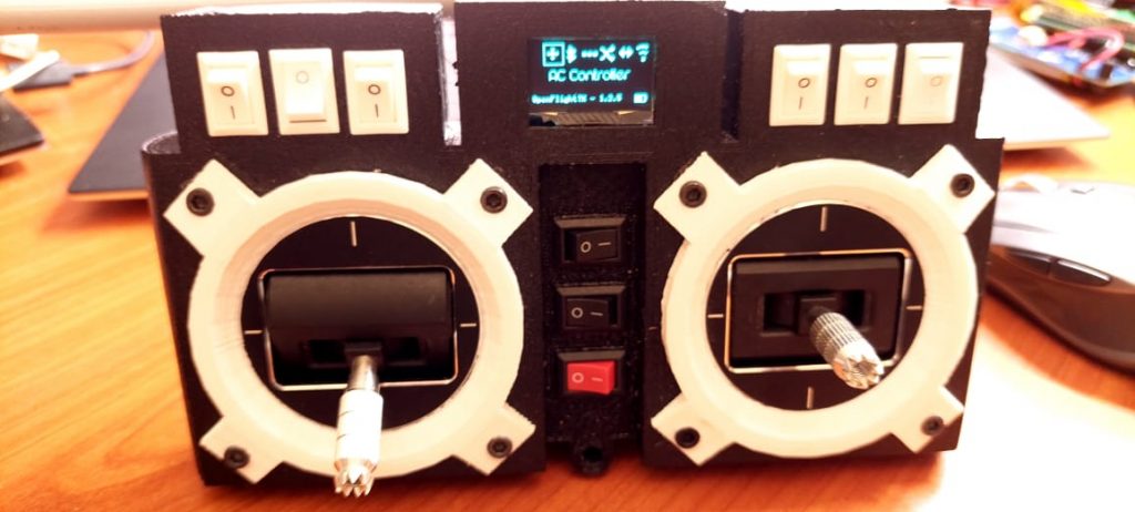
Yeah, A little bit difference but almost there. I used:
– 9 Push switches 10x15mm
– ESP32 16MB
– 2 x FrSky M10 Gimbal Hall Effect Sensor
– 1 x 0.96″ OLED
– 30AWG silicon wires
– 1 x 18650 Battery Holder
– Custom design PCB and fabricated by JLCPCB
– 1 x EByte E01-2G4M27D
– Lots of SMD components (Look at the schematic)
I had perfected the menu display without using any buttons but using the gimbal to scroll through the items. Trying to save some I/O pins for the switches so I am having more channels to play with. I used to have a charger module built in with this but for this version I had removed it for the simplicity. Just charge the 18650 cell with a proper charger module and swap another piece if is low power.
The schematics:
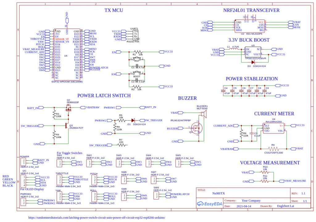
WARNING: Still in progress of development. The current meter is not usable for this as the current draw was less than 1A. The designed was for quads that is draining > 1A. I will need to fix that and also the buzzer driver, I had put the MOSFET wrongly. I will need to change that in future. For now I had temporary disabled the buzzer. As well as the power latch section, I cant wait for the components arrival. I had altered to an ordinary power regulator module which stabilized the voltage from 4.2v -> 3.3v. The minimum operating voltage is about 3.5v as I had measured.
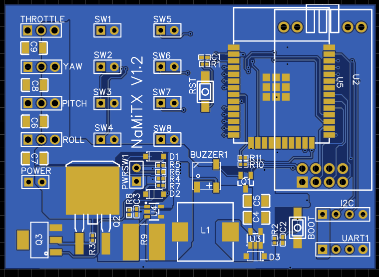
I will share the gerber later once I had perfected the issues.
Initial plan was thinking to have it run under 2.5v but the chip havent arrive until now. No worries, I am going to build some more with a better design soon.
Anyone interested to the code? 🙂
You can get it from my personal GiT server -> https://git.bertfpv.com/englebert/OpenFlightTX.git/
Next topic will be the receiver and the details. I will write up and post it here as well as the code. The receiver is running on SBUS signal. Stay tune….