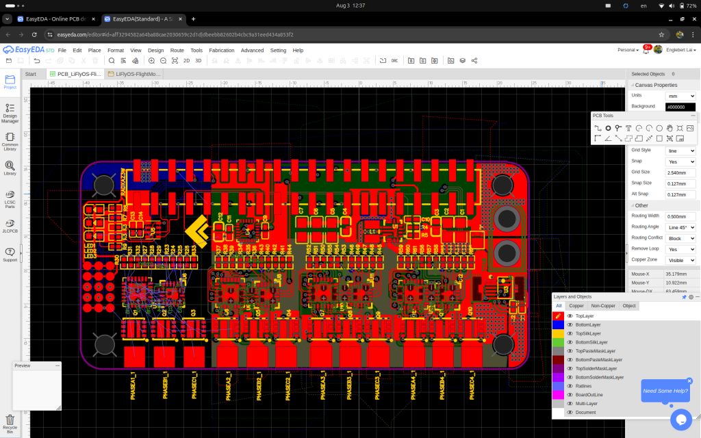
I am building something fun for everyone. It will be running on Linux. I hope this works out. Now left 1 more section to be completed and sending it for fabrication…. Stay tuned.

I am building something fun for everyone. It will be running on Linux. I hope this works out. Now left 1 more section to be completed and sending it for fabrication…. Stay tuned.
No doubt the power of digital system. Only 100mW and the quality never dropped.
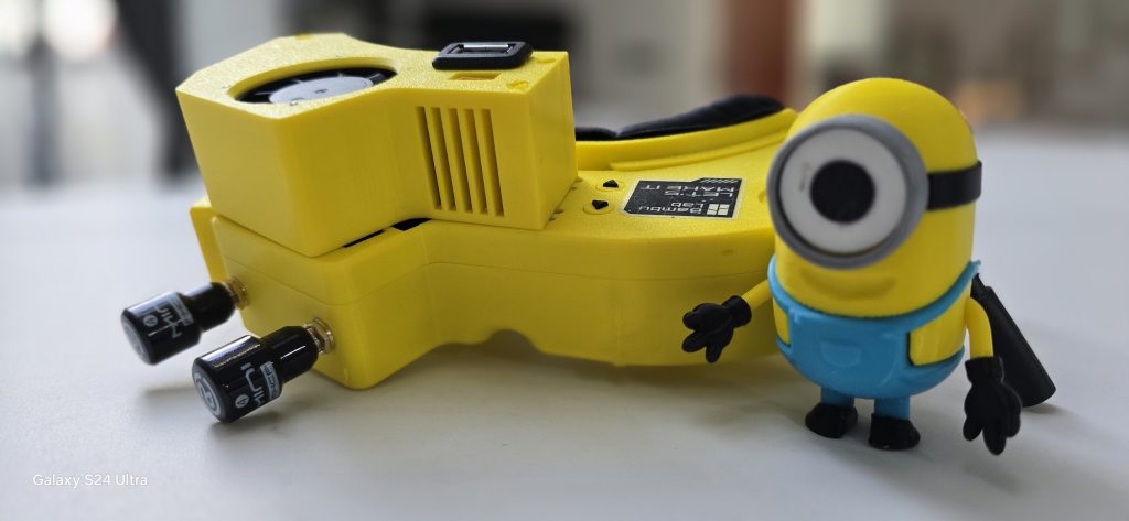
The RubyFPV is really astounding!!! Very stable and solid. I had migrate my Eachine ev100 into a custom designed 3d case, putting the Pi Zero 2W, USB hub module, 5 DCDC regulator, bl-m8812eu2 WiFi module card and etc into one single case. I had chosen yellow because it looks like minion.
Below is my build video:
Subscribe my channel for more updates.
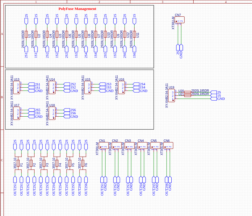
Previously had designed and not working great as not added any fuse and polyfuses between the balancer lead and battery. This round I had made it to protect some serious shortcircuits that we never thought it will happened. Safety first.
What I had done this round is added the poly fuses to all the balancer leads. This will reset after it breaks off. Just cool it down and the fuse will be back to normal. For the battery leads, all added a fuse holder with fuse. This will allows the fuse to be easily changed if ever shortcircuit is happened.
Why 2S? Well, all my designed for my current quad is using only 2S and I am limiting to 2S for small quads that are around 3 inches frame only. Also all the motors I am currently using are max at 2S power. I prefer it to be small and fun.
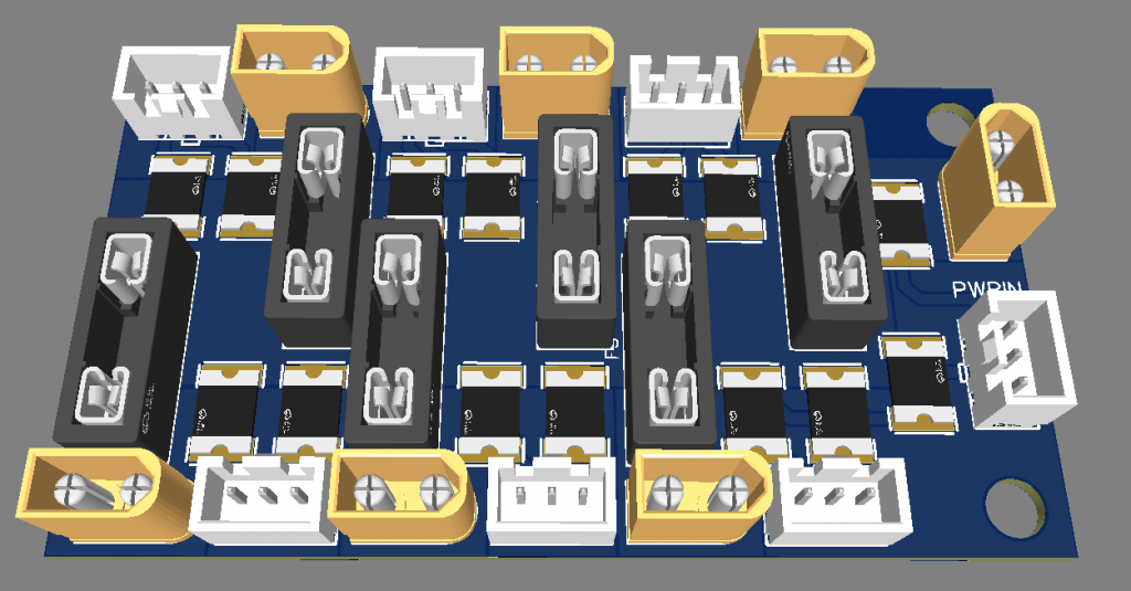
The Schematic as below:
Have a nice day!
After so many years, finally able to fiy in acro mode. I had been training myself intensively over simulator until I am confident enough to try it on REAL world. The system also had upgraded with digital video feed and is truly a whole new game.
https://www.youtube.com/watch?v=1YlN5Kuw9E

Something coming up soon. This little guy will be driven by 2S battery. Yeah… meaning going to running on my latest 2S ESC version. Will keep you guys update soon… Stay tuned….
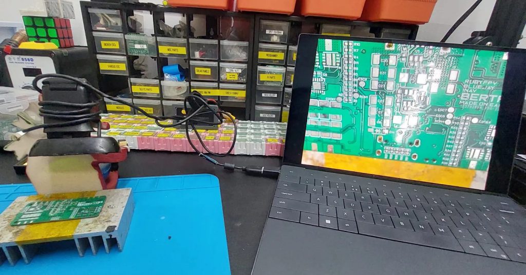
Had been really long busy year. Finally able to fork out some spare time to kickstart back my long waited project. This will be combining the Flight Controller, 4 x ESC, Current Sensor, High Efficient power regulator for 3.3v and 5v, Powered by 2 x 18650 battery and many more!!
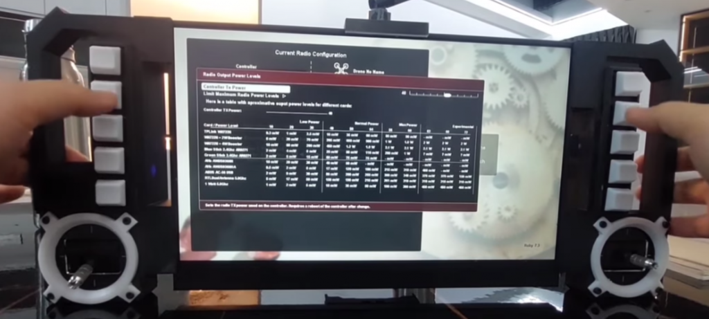
Hope to get this done quick then can start to fly with my new BigRC (Installed with RubyFPV system and custom controller using ESP32). This will be mini long range quad!!!
Next is to design a suitable frame for the quad while assembling the parts one by one……
Stay tuned….
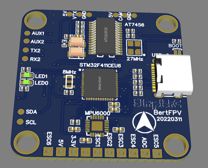
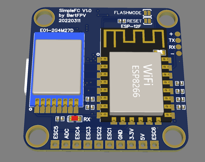
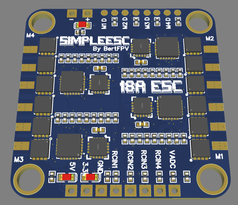
Finally had send this latest version for PCB fabrication. I had been busy recently but able to fork out some time to continue this hobby.This year new objective 2022 is to make this one work better than previous version. What I had done:
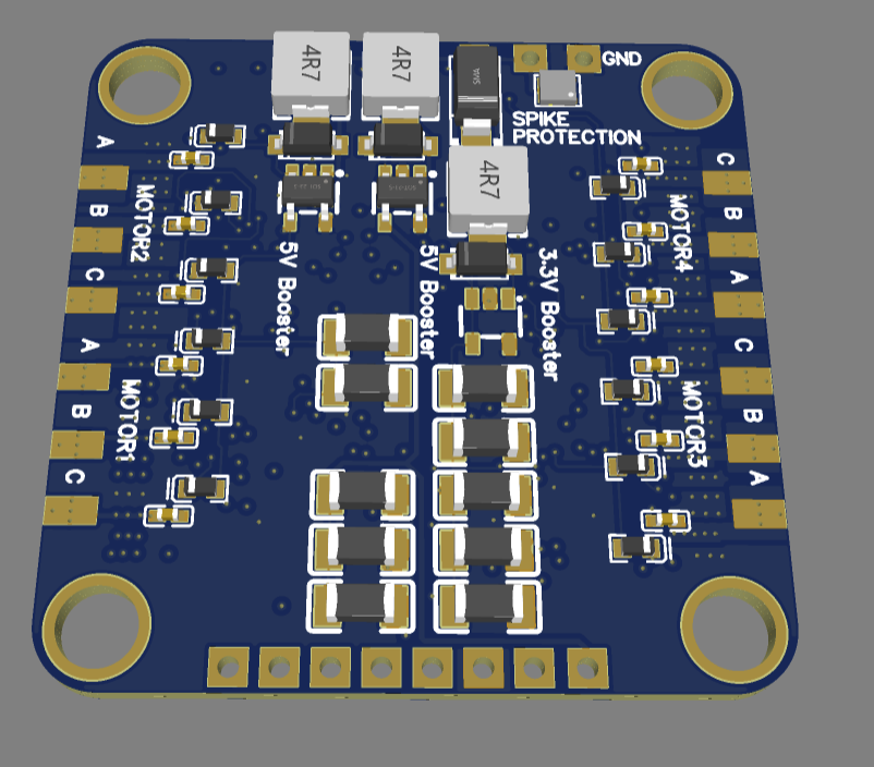
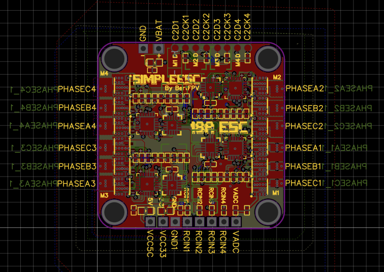
1. I separated the ESC with Power Supply section to one board
2. For the FC board, just plainly MCU, Gyro, Receiver.
3. Now my custom receiver is upgraded to ESP12F. Sounds like expressLRS, but is not. It was my long time ago receiver until now. It was running on atmega328 but I had migrated to this ESP32 and now shrinking it. Also using E01-ML01 as the receiver (NRF24L01P compatible)
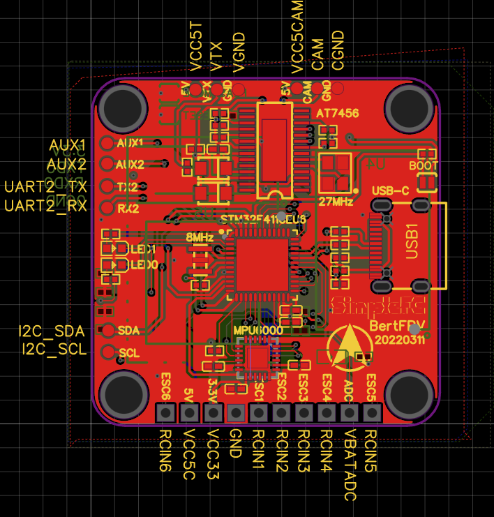
4. I call it SimpleFC because I want it to be simple and clean. So, this round I had removed BARO and also using STM32F411CEU6 microcontroller. How I did that? I reverse engineered from the code. Based on the code, I mapped back the pins and build backs the schematic. Is a pretty fun process.
5. Of course now is year 2022, we need USB C. I had found pin layouts from USB C pins and successfully linked it back to the board. No longer need to carry another USB cable for that. I know some are using WiFi cheap for flashing but I still prefer to have cables.
6. Both the board sizes are: 37mm x 37mm with 1mm thickness and 4 layers.
Interested? Support me via -> https://www.buymeacoffee.com/bertfpv/schematic-for-simple-fc-simple-esc
You will be able to download the schematics.
Specifications:
FC:
– USB-C port
– STM32F411CEU6 (FC MCU)
– MPU6000
– OSD
– ESP12F (Receiver MCU)
– 6 ESC outputs
– AUX1, AUX2 can be used for RSSI (Next version will link the RSSI)
– 2 hardware serial ports
– 1 I2C port
– Supports INAV or BETAFLIGHT
– 1 x CAM port with 5V power
– 1 x VTX port with 5V power
ESC:
– 4in1 ESC
– 18A each phase
– Including 3.3V and 2x 5V buck booster
– Voltage sensor
– Only support 1S (Supported voltage from 2.0v ~ 4.2v) Once the voltage hits 2.5v motor spins but not enough rpms to maintain. Only able to power up the electronics.
– Supports BlueJay and BLHeli_S firmware.
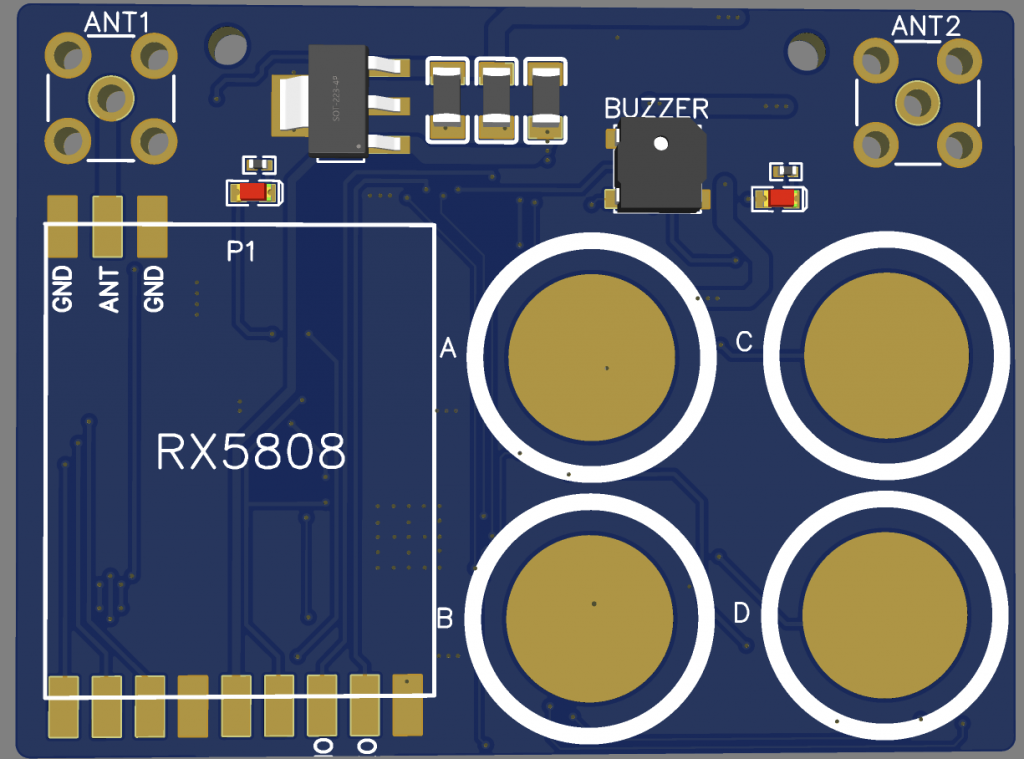
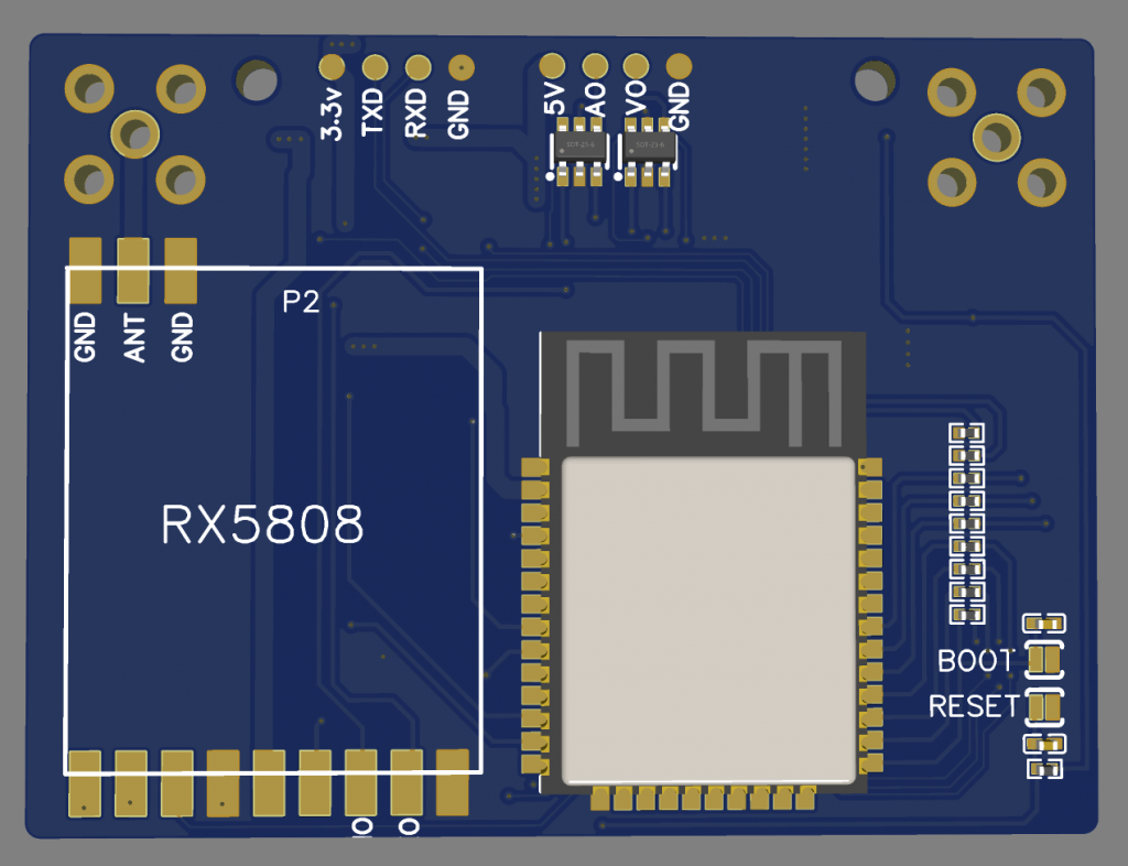
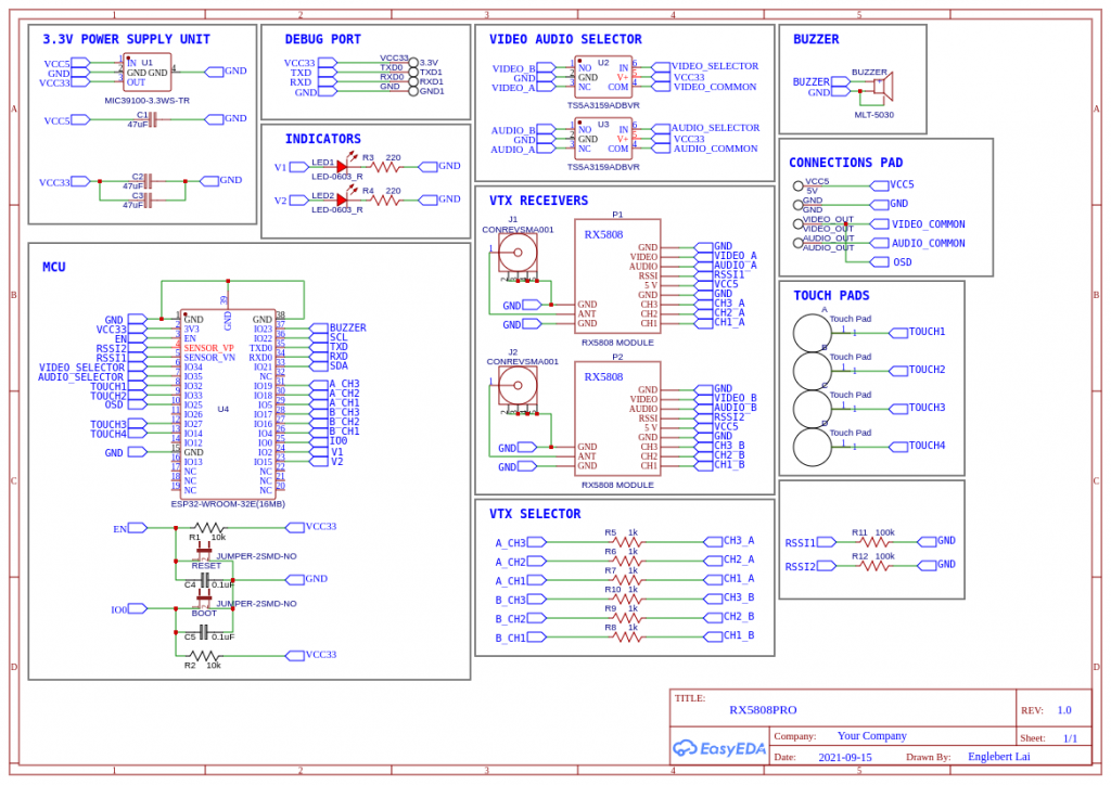
Recently flying my nano quad, felt a bit scary without a second receiver on the goggle. I had to keep moving my head to get the best reception for the video feed. Finally, I learned about the little display thing on every one’s FPV goggle is actually dual RX5808 receiver with some firmware that keep switching to the best video feed signal. My Eachine EV-100 having dual antenna but is not a very good in handling diversity. I found a few good opensource projects and saw their designs very good but I need audio output as well for the receiver so decided to make my own version. The board already sent for fabrication and now left the firmware to be developed and make it working. I had already tested the tv composite output is working and is very fun to built this diversity vtx receiver. Wish me luck!
The specifications:
– Dual RX5808 Receiver
– Video Out
– Audio Out
– 4 Touch Sensors
– minimal components
– single PCB with dual layers
– 5V input
– Using software SPI mode
– Buzzer
– 2 LED indicators
– OSD in display
– Web OTA
PCB DESIGNS:
Had done all my testing and flying on this version. Found some bugs and fixed it. The problem was during 3.6v and above the output will be getting higher linearly. So I had added a diode with a 0.6v forward drop voltage. This enables it to have a stable output at 3.3v.
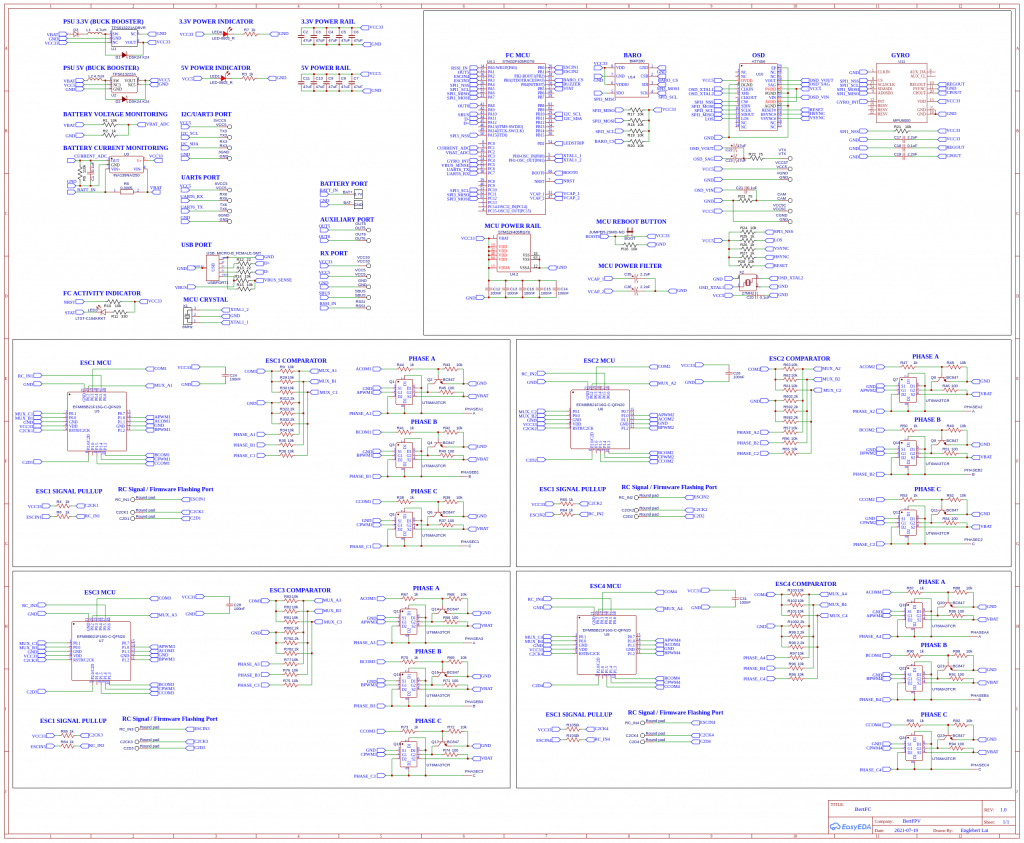
This board design is only meant for 1S. Meaning operating voltage is in between 2.0v ~ 4.2v. Higher than that you need to modify the buckbooster part into a 3.3v LDO as well as the 5v power line to a 5V LDO. I modified this from OMNIBUSF4PRO to my custom made version. I removed SDCard as the blackbox to save more space for the All-In-One board.
For the USB port, I am not supplying the 5V to the board. It needs to be power up from the 1S battery. I dont want it to overload my laptop 5V to it or maybe accidentally shorted the board cause the laptop 5V logic all burned off. That is why I designed it not to supply to the board but needs to power up with the battery or some power supply regulator to the board before the USB port is recognized by the laptop or PC.
For the ESC part, is designed to be running on 1S. The MOSFETS are running at 5A maximum at continuous and pulse drain at 12A. Due to the ESC I had flashed with BlueJay, it should be able to handle a bit more then 5A. The trigger level (Vgs) of the MOSFET is very low, there isn’t need any MOSFET drivers. The only thing, we need to invert the output from one of the line to drive the P-MOSFET. If intended to driver higher current, try to find another type of MOSFET and replace it. The ESC design also can be used those single MOSFET rather 2-in-1 MOSFET. It will be bigger but reliability wise should be better. When designing a higher voltage ESC, meaning more than 1S, you will need higher current rating of the MOSFET and may need to add a driver or custom transistor to drive the MOSFET. I will be working on higher “S” ESC in near future. These designs are came from tinyPEPPER – https://fishpepper.de/projects/tinypepper/ with some modifications done to the schematic where it enables it to run at a very low voltage to provides stable 3.3v to the EFM8BB21F16G and is sharing with the main board FC’s 3.3v powerline. This will save some costs of making this FC. One 3.3v buckbooster that powers up the FC, Gyro, Baro, VTX, Cam, ESC and etc. It will not draw more than 1A as I had tested so far. The VTX is powered up by another 5V buckbooster power line. So is totally not affecting each other.
For the FC firmware, I am using INAV 3.0.1. I am a INAV fans. For betaflight it will work too but need to changed to OMNIBUSF4 board for the firmware.
Initially, the ESC’s EFM8BB21F16G are blank. You need to flash in the firmware using C2CK and C2D pins before you can flash the ESC firmware over serial passthrough method. Once if flashed, all ESCs will be appeared in the INAV configurator. You even can use the BLHeli or BlueJay configurator to set your preferred settings. If you need to know how to flash in the ESC firmware, you can read from here -> https://www.bertfpv.com/how-to-flash-blheli_s-firmware-to-efm8bb21f16g/. You will be able to have a full control of your hardware and without fear of broken it again.
I will include the gerber file on the next version. For this version, I still need to fix the distance between the pads and the SMD components. It needs a very steady hand to solder the wires on it. So I am going to built version 2.0 very soon.
Sponser this project:
https://www.buymeacoffee.com/bertfpv
Below is the schematic diagram for this All-In-One flight controller I had built. I had included both PDF and PNG. Time to built it your own and fly it. Is a very great experience and understanding how the whole quad works. Stay tune.
